What is LVDT?
LVDT is a passive transducer. LVDT stands for Linear Variable Differential Transformer. It is also an electromechanical-based inductive transducer that converts rectilinear movement into an electrical signal.
In simple, we can say an LVDT is a passive inductive transducer that converts Linear displacement into an AC Electrical signal.
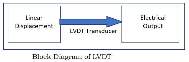
LVDT is a type of secondary transducer which means the primary transducer is used to convert the physical parameters like force, weight, pressure, tension into displacement and then using LVDT the respective electrical output is obtained. LVDT has high accuracy level so it is also used as an Inductive sensor
What is the working principle of LVDT?
The linear variable differential transformer is a specially designed transformer. The LVDT works under the principle of mutual inductance effect.
Under transformer theory, the two coils are coupled by an alternating magnetic field. When AC voltage is applied to the primary winding, the magnetic field is produced. This magnetic field induces a current in secondary winding, therefore, there is an induced voltage in the secondary coil.
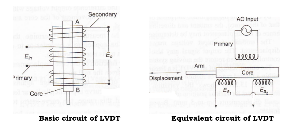
Similar to this LVDT consists of one primary winding P, two secondary windings(S1& S2) and a soft iron core. The construction of LVDT is shown in below figure. The secondary windings are arranged on a cylindrical former with a movable soft iron core. The primary winding is surrounded by two identical secondary windings (S1 and S2), each of which has an equal number of turns. The secondary windings are connected in a series opposition.
The soft iron core arm is connected to the part to which the displacement is to be measured. This iron cores are subjected to hydrogen annealing in order to reduce harmonics, the residual voltage of the core, and to increase sensitivity. To cut down on eddy current losses, the movable core is additionally laminated. LVDT is also installed inside a stainless steel as it provides electrostatic and electromagnetic fields.

Working of LVDT
A source of constant amplitude AC power, energize the primary winding, P, of the LVDT. The core then connects the nearby secondary windings S1 and S2, the magnetic flux is created. According to the position of the core, the working of LVDT can be divided into 3 cases.
Case 1:- LVDT Core is in null Position:
V0= V1-V2=0
Case 2:-LVDT Core is moved left of null position.
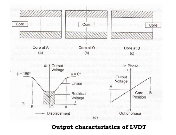
When the core of LVDT core is moved to left, then more flux links with coil S1 than S2. Hence voltage induced in S1 is greater than S2. The net output voltage is V0=V1-V2 is positive.
Case 3:- LVDT Core is moved Right of null position.
When the core of LVDT core is moved to right, then more flux links with coil S2 than S1. Hence voltage induced in S2 is greater than S1. The net output voltage is V0=V1-V2 is negative.
Output characteristics of LVDT
Output characteristics of LVDT is observed from the response of output voltage with respect to displacement. In fig. (c) we can observe initially response is linear over a small range of displacements later it becomes non-linear. For zero displacement, we can also observe a small voltage. This voltage under zero displacement is called residual voltage. Magnitude of residual voltage is less than 1% of maximum voltage.
Cause of Residual Voltage in LVDT
- Due to harmonics present in ac power supply
- Harmonics produced in iron core.
- Stray Magnetic Fields & temperature effects.
Real case Applications of LVDT
- Fuel Control: A LVDT aids in ensuring that fuel is always used as efficiently as possible as it relates to fuel regulations. Later it ensures that the gasoline is released at the precise moment when it is needed, providing you the ideal performance to fuel ratio.
- Engine Bleed Air Systems: LVDT is used to assist in controlling the volume of air bleed into engine bleed air systems.
- Thrust Vector control: The LVDT essentially places the vector on the bottom of the missile or rocket when it comes to thrust vector control. In this manner, it is possible to change the engine’s thrust direction in order to regulate the rocket’s angular velocity or the aircraft’s altitude.
- Defense Satellites & lunch systems: Defense satellites and launch systems are some of the most typical applications for LVDTs in space. One advantage of utilizing LVDTs for defense satellites is that they aid in angling the satellite panels toward the sun. This makes it easier for us to transfer solar energy to the satellites so that they can remain in orbit. LVDTs enable for excellent performance in launch systems while requiring little maintenance. When working with launch systems, which may be frequently inaccessible and challenging to maintain, this is excellent.
- Valve Pitch: Actuators can be used to check that the valve actuator moved into the correct position and that it worked as intended.
- Valve position feedback: In order to help regulate the actuator and monitor and maintain the valve position, linear displacement transducers provide feedback regarding the valve position.
- Displacement measurement
- Measure Force, weight, Pressure
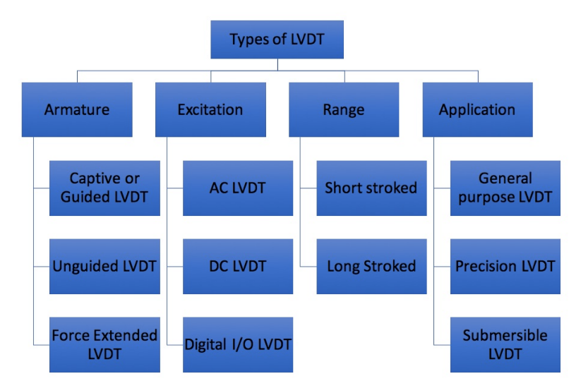
Classification of LVDT Transducer
The LVDT classification is shown in below table. It is classified based on the
- Armature
- Excitation
- Range
- Application
LVDT types based on armature
- Unguided Armature: Armature fits loosely in coil bore cavity. Proper installation ensures axis accuracy. This eliminates friction and wear. This type has infinite resolution, repeatability and fatigue-free durability. Free armature is best for high-speed, short-range applications.
- Guided (Captive) Armature: This type uses a low-friction bearing assembly to guide and restrain the armature. These are suitable for long working ranges. Guided armature prevents misalignment.
- Spring Extended Armature: This armature is similar to guided armature LVDT, but it has an internal spring to extend it continuously. This maintains contact with the object.
LVDT types based on Applications
- General Purpose LVDT: LVDT is used in many industrial and research applications.
- Precision LVDT: This type of LVDT is preferred for sensitive gauging and quality control applications
- Submersible LVDT: This type of LVDT is used in industrial and research situations with corrosive gases and fluids, high temperatures, and vibrations, etc., with fully sealed equipment.
LVDT types based on range of operation
- Short stroked LVDT: 1. Short stroked LVDT works under the full-scale linear ranges from ±0.01 inch (±0.25 mm) to ±0.5 inch (±12.7 mm) This precision LVDT with a short stroke works well in situations that need for dynamic measurement but have limited space.
- Long stroked LVDT: Long stroked LVDT works under the Full-scale linear ranges from ±0.5 inch (±12.7 mm) to ±18.5 inch (±470 mm) The transducer has a spring return armature and the transducer can be easily adapted to work with the majority of industrial measuring applications. This type of transducer has high resolution, built-in extended life, good repeatability.
LVDT types based on Excitation
- AC LVDT: The AC LVDT is excited by an AC voltage with a nominal frequency of 2.5 kHz and a frequency range of 50 hertz to 25 kHz. Compared to their DC equivalents, AC-operated LVDTs are more accurate and more compact. They can sustain much larger fluctuations in operational temperature than the DC LVDT can.
- DC LVDT: The DC LVDT consist of an AC operated LVDT, oscillator, carrier generator/ signal conditioning circuit. Characteristics of LVDT remains the similar to AC LVDT. Based on application, user can select AC or DC LVDT.
- Digital I/O LVDT: A digital I/O interfacing board can be connected to analog device. An interface board is feeding the input and output digital signals in parallel to a computer. Using a digital I/O device makes it possible to monitor (read) the status of measuring devices.
Advantages & Disadvantages of LVDT
Advantages of LVDT
- LVDT output is very high
- Power consumption of LVDT is very low.
- Measurement range is very high.
- LVDT is small in size and has excellent repeatability.
- LVDT has high resolution.
- Easy to align & not affected by external Environment.
- Direct Conversion to electrical signal.
- Fast Dynamic response
Disadvantages of LVDT
- LVDT gets damaged by temperature
- Vibration due to displacement can affect the performance of output.
- For small output, large displacement is applied.
- Since LVDT reacts to magnetic fields by moving away from them, a device to prevent magnetic field drift is continually required.
- LVDT is also sensitive to stray magnetic field.
Some Useful Questions related to LVDT
1. What is full form of LVDT?
Linear Variable Differential Transformer
2. What is LVDT?
A Device that converts convert rectilinear motion or linear displacement into electrical signal
3. What is difference between rectilinear motion & Linear motion
| Linear motion | Rectilinear motion |
| Linear motion is defined as when object is moving in a straight line or along a curved line in a plane. | Rectilinear motion is defined when an object moving only in straight line. |
4. What is a transformer?
A passive component which transfers electrical energy /signal from one circuit to other.
5. Why LVDT is called a differential transformer?
The difference between voltages of two windings (secondary coils) is obtained and thus the name – Linear Variable Differential Transformer.
6. Which is other words of secondary coil?
Secondary coil is called as pick up coils.
7. What is the principle behind LVDT?
LVDT works in the principle of mutual inductance.
8. Write short notes on LVDT.
LVDT converts mechanical to electrical energy. On a hollow cylindrical former are one primary and two secondary windings. A soft iron core that slides within the hollow former affects the primary and secondary coils’ magnetic coupling.
9. Which material is used in LVDT?
An LVDT core is a permeable magnetic cylinder that couples the primary and secondary coils inductively. The core is usually made of ferromagnetic iron.
10. List some of the characteristics of LVDT
- Electromechanical device.
- Can operate at temperature up to 6500C.
- Long life cycle.
- High reliability.
11. What is meant by RVDT?
RVDT stands for Rotary Variable Differential Transformer. RVDT is an electromechanical transducer used to measure angular displacement. The obtained output is an electrical signal proportional to angular displacement.
12. How is LVDT different from RVDT?
- LVDT converts linear displacement into electrical signal whereas RVDT converts angular displacement into electrical signal.
- In LVDT the core is rectangular shaped whereas RVDT is cam Shaped.
- LVDT is used in measuring force, pressure weight, displacement whereas RVDT is used in controlling application such as turbine operation, process control industry.
13. A LVDT produces an RMS output voltage of 2.6V for displacement of 0.4ìm. Calculate the sensitivity of LVDT.
Sensitivity is defined as the ratio between the output signal & the measured property.
Output of LVDT is a voltage signal = 2.6 V [RMS output Voltage]
Measured Quantity = 0.4ìm [Displacement]
Sensitivity (S) = Output voltage (V) / Displacement Measured (m)
= 2.6/0.4
= 6.5V/μm
14. List the advantages of LVDT.
- High range of displacement measurement.
- Friction and electrical isolation.
- Immunity from external effects.
- High input and high sensitivity.
- Ruggedness.
- Low hysteresis and low power consumption.
15. List the limitations of LVDT.
- LVDT are magneto sensitive.
- Dynamic response is limited.
- Temperature also affects the transducer


